A Detailed Explanation of the Planing Process of Industrial Planers
In the woodworking industry, industrial planers are core equipment for precision surface treatment and dimensional control of wood. The scientific and stable nature of their planing process directly determines the quality and efficiency of wood products. From panel processing for solid wood furniture to cutting wooden components to specifications, planing remains a key step in the fine processing of wood. This article will comprehensively analyze the planing process of industrial planers from four perspectives: equipment structure, process flow, core principles, and key operational points, providing a systematic technical reference for industry practitioners.
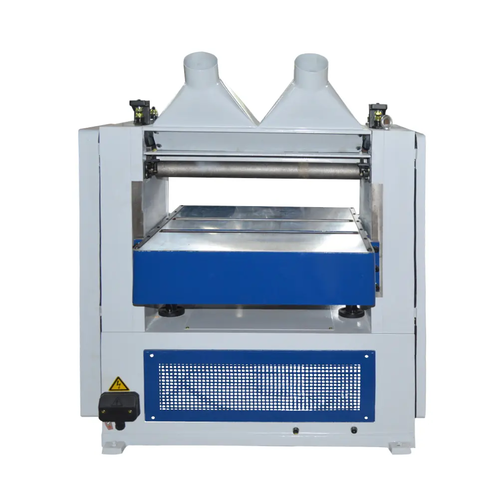
I. Core Components and Functional Positioning of Industrial Planers
Industrial planers are mechanical equipment that cut wood surfaces using a high-speed rotating planer blade. Their structural design is centered around three core requirements: efficient cutting, precise positioning, and stable operation. Different types of planers (such as flat planers, press planers, and four-side planers) have structural differences, but their core components are common and primarily include the following:
(I) Power Drive System
The power drive system is the heart of the planer’s operation and typically consists of a three-phase asynchronous motor, a reduction gear, and a drive belt. The motor’s power, after being regulated by the reduction gear, is transmitted via the drive belt to the planer shaft, driving the blade at high speed. The power system can adjust the speed according to the processing requirements. The planer shaft typically operates in a range of 3000-6000 rpm. Higher speeds improve cutting accuracy, while lower speeds are suitable for cutting difficult-to-cut materials such as hardwood.
(II) Cutting Execution System
The cutting execution system is the core of the planing action and consists of the planer shaft, planer blade, and a shaft locking device. The planer shaft is made of high-strength alloy steel and has a hardened surface for enhanced wear resistance. Planer blades are typically made of high-speed steel (W18Cr4V) or carbide. Blades with varying cutting edge angles (generally ranging from 25° to 45°) can be selected based on the hardness and surface requirements of the wood being processed. The shaft locking mechanism utilizes a wedge block or hydraulic locking mechanism to prevent the blade from shifting during high-speed rotation, ensuring safe and stable cutting.
(III) Feed Positioning System
The feed positioning system determines wood processing accuracy and feed efficiency and primarily consists of three components: the worktable, feed roller, and guide plate. The worktable is made of cast iron and ground to a flatness tolerance of ≤0.02mm/m. The feed roller is made of rubber or polyurethane and uses pneumatic or hydraulic pressure adjustment to prevent slippage and deviation during feeding. The guide plate remains perpendicular to the worktable and its positioning accuracy can be adjusted using a micrometer to within 0.01mm, ensuring the required straightness of the wood’s sides. (IV) Safety Protection System
The safety protection system is essential for industrial planers and includes a planer shaft guard, an emergency stop device, and a safety sensor. The guard is made of transparent polycarbonate, ensuring the operator’s view of the machining process while effectively blocking flying chips. The emergency stop device has a response time of ≤0.1s and can immediately cut off the power supply in the event of an emergency. The safety sensor uses infrared sensing technology to automatically shut down the machine if a person approaches the danger zone of the planer shaft, preventing accidents.
II. Standard Planing Process and Operational Logic
The planing process on an industrial woodworking planer follows a closed-loop process of “positioning – feeding – cutting – detection.” The operational specifications of each step directly affect the final machining quality. Taking the planing of solid wood panels as an example, the standard process is as follows:
(I) Pre-processing Preparation
Material Pretreatment: Test the wood’s moisture content to ensure it’s between 8% and 12% (the optimal moisture content range for solid wood processing). A high moisture content can easily cause deformation after processing, while a low moisture content can easily cause cutting cracks. Also, remove impurities such as nails and sand from the wood surface to prevent damage to the planer blade.
Equipment Commissioning: Adjust the worktable height based on the wood thickness and processing requirements (control the planing depth; a single planing depth generally does not exceed 3mm, and 2mm for hardwood). Adjust the parallelism between the guide plate and the planer shaft to ensure the flatness of the processing surface. Check the sharpness of the planer blade edge; sharpen it if the edge wear exceeds 0.2mm.
Safety Check: Verify that the protective cover is securely installed, the emergency stop device is functioning properly, and the safety sensor is unobstructed. Operators must wear protective equipment such as protective glasses and non-slip gloves. (II) Core Processing Stage
Positioning and Clamping: Place the wood’s reference surface against the worktable, with the side against the guide plate. Use the feed roller pressure adjustment knob to set the appropriate feed pressure (generally 0.3-0.5 MPa, with the lower value for softwood and the higher value for hardwood).
Feed Cutting: Start the machine. After the planer shaft reaches its rated speed, slowly push the wood onto the feed rollers, which then move the wood through the planer shaft’s processing area at a constant speed. The feed speed is adjusted based on the wood’s hardness and planing depth, generally between 3-15 m/min. Reduce the feed speed for hardwood or greater planing depths.
Multiple Cutting: For wood with large thickness variations, adopt the “multiple, small cuts” principle, gradually achieving the target thickness through multiple planing passes. Inspect the wood’s surface quality after each planing pass. If any issues such as wavy lines or undercutting occur, adjust the worktable height or feed speed immediately. (III) Post-Processing Inspection
Dimensional Accuracy Inspection: Use a vernier caliper to check wood thickness tolerance (generally required to be ≤ ±0.1mm), a straightedge to check surface flatness (tolerance ≤0.05mm/m), and a square to check the perpendicularity of adjacent surfaces (tolerance ≤0.1mm/m).
Surface Quality Inspection: Visually inspect the wood surface for defects such as burrs, scratches, and cracks. Use a surface roughness tester to check surface roughness (generally, furniture wood requires Ra ≤1.6μm, and construction wood requires Ra ≤3.2μm).
Equipment Maintenance: Turn off the machine, clean wood chips from the workbench and planer shaft, inspect planer blade wear, and re-lubricate the feed system’s lubrication points to ensure stable operation the next time the machine is used.
III. In-Depth Analysis of the Core Principles of Planing
The essence of planing is the precise removal of surface material from the wood through the relative motion of the planer and the wood. This core principle involves the integrated application of cutting mechanics, material mechanics, and kinematics, primarily encompassing the following three aspects:
(I) Principles of Cutting Motion and Cutting Quantity
There are two basic motions in the planing process: the rotational motion of the planer (the main motion) and the linear feed motion of the wood (the feed motion). The main motion provides the cutting force, and its speed v (unit: m/s) is determined by the planer shaft speed n (unit: r/min) and the planer shaft diameter D (unit: mm), calculated as v = πDn/60,000. The feed motion determines cutting efficiency, and the feed speed f (unit: m/min) is directly related to the feed roller speed and roller diameter. Properly matching the three key elements of cutting parameters (planing depth ap, feed rate f, and cutting speed v) is key to ensuring machining quality:
Planing depth ap: refers to the thickness of wood removed per planing pass. Excessive planing depth ap can cause excessive force on the planer, resulting in vibration and surface ripples. Excessive planing depth ap: refers to the thickness of wood removed per planing pass. A planing depth of ap, which is too large, can cause excessive force on the planer blade, causing vibration and resulting in surface ripples. A planing depth of ap, which is too small, can reduce machining efficiency. It is generally adjusted based on the hardness of the wood. For softwoods (such as pine), the maximum ap is ≤3mm, and for hardwoods (such as rosewood), the maximum ap is ≤2mm.
Feed rate f: refers to the number of times the planer cuts the wood per 1mm of advance. It is related to the number of blades on the planer shaft: the greater the number of blades, the greater the feed rate and the smoother the surface finish.
Cutting speed v: Hardwood machining requires a higher cutting speed (generally 50-60 m/s) to reduce cutting resistance. For softwood machining, a lower cutting speed (generally 30-40 m/s) can be used to avoid surface fuzz.
(II) Principles of Wood Cutting Deformation and Removal
As an anisotropic material, wood cutting involves complex deformation and fracture mechanisms. When the planer blade contacts the wood, it initially compresses the wood, causing elastic deformation in front of the blade. As the planer continues to move, the elastic deformation transforms into plastic deformation, generating shear stress within the wood. When the shear stress exceeds the wood’s shear strength, the wood shears and fractures, forming chips that are expelled.
The shape of the chips directly reflects the effectiveness of the cutting process:
Continuous ribbon-shaped chips: Commonly seen in softwoods, at high cutting speeds, and with small planing depths, indicate a smooth cutting process and good surface quality.
Knotty chips: Commonly seen in hardwoods, at medium cutting speeds. If the knots are uniform, the surface quality is acceptable. Irregular knots may indicate wear on the planer blade or improper cutting rate.
Splintered chips: Commonly seen in hardwoods, at large planing depths, indicate excessive cutting resistance, which can easily lead to surface cracks and require adjustment of the cutting rate. (III) Precision Control and Error Generation Principles
Planing accuracy primarily includes dimensional accuracy, form accuracy (flatness and straightness), and positional accuracy (perpendicularity). The causes of error can be analyzed from three perspectives: equipment, materials, and operation:
Equipment Factors: Worktable flatness errors can directly lead to surface flatness deviations; excessive radial runout of the planer shaft (generally required to be ≤0.01mm) can easily cause surface waviness; uneven feed roller pressure can cause wood feed deviation, resulting in dimensional errors.
Material Factors: The direction of the wood grain significantly influences machining accuracy. Cutting with the grain results in low cutting resistance and a smoother surface; cutting across the grain results in high cutting resistance and is prone to chipping and burrs. Cutting with the diagonal grain is somewhere in between, requiring adjustments to the cutting speed and feed direction.
Operational Factors: Inaccurate worktable height adjustment can lead to planing depth deviations; inaccurate guide plate positioning can result in perpendicularity deviations between adjacent surfaces; and unstable feed speed can result in unsatisfactory surface roughness.
IV. Practical Optimization of the Planing Process and Equipment Selection Recommendations
(I) Common Problems and Solutions During Practical Operation
Surface ripples: The main cause is excessive radial runout of the planer shaft or excessive table flatness error. Solution: Check the planer shaft runout and replace the bearings if it exceeds the standard; repair the table by grinding to ensure flatness.
“Broken ends” of the wood: This is caused by insufficient feed roller pressure or improper height connection between the table and the planer shaft. Solution: Increase the feed roller pressure to 0.4-0.5 MPa; adjust the front and rear end heights of the table to ensure smooth entry and exit of the wood from the cutting area.
Surface burrs and chipping: This is often caused by blunt planer blades or too low cutting speeds. Solution: Sharpen the planer blade to ensure cutting edge sharpness; increase the cutting speed to at least 50 m/s for hardwood cutting.
Unstable dimensional accuracy: This is caused by fluctuating feed speeds or loose guide plates. Solution: Check the feed system motor speed stability and replace worn drive belts; tighten the guide plate locking bolts and recalibrate positioning accuracy.
(II) Industrial Planer Selection Criteria and Suitable Applications
Different types of industrial planers are suitable for different processing needs. When selecting a planer, consider the three key criteria: processing material, processing accuracy, and production efficiency:
Flat Planers: Primarily used for flattening wood surfaces to achieve a flat surface. They are suitable for surface preparation of solid wood panels and rough processing of furniture panels. When selecting a planer, consider the worktable length (generally 1500-3000mm, with long tables suitable for processing long materials) and the maximum planing width (common specifications are 400-800mm).
Press Planers: Using simultaneous cutting of upper and lower planer shafts, they achieve precise control of wood thickness. They are suitable for calibrating the thickness of solid wood panels and finishing flooring substrates. When selecting a planer, focus on the maximum processing thickness (generally 100-200mm) and thickness accuracy (required to be ≤±0.05mm). Four-Side Planer: This machine can process all four surfaces of wood simultaneously, achieving “one-feed, four-side shaping.” It’s suitable for batch processing of profiles such as door and window frames and furniture columns. When selecting a model, consider the processing width range (typically 20-200mm), feed speed (up to 30m/min), and number of tool sets (typically 4-6; more sets improve processing accuracy).
(III) Long-Term Strategies for Equipment Maintenance and Process Optimization
Regular Maintenance Plan: Establish a maintenance system of “daily cleaning, weekly lubrication, monthly calibration, and annual overhaul.” Clean cutting chips and oil daily; refill lubrication points of the feed and drive systems with specialized lubricant weekly; calibrate the worktable flatness, guide plate verticality, and planer shaft runout monthly; and annually disassemble and overhaul the motor and reduction mechanism, replacing worn parts.
Process Parameter Optimization: Develop unique process parameter tables for different wood types. For example, when processing pine, we use “planing depth 2.5mm, feed speed 12m/min, cutting speed 40m/s”; when processing redwood, we use “planing depth 1.5mm, feed speed 8m/min, cutting speed 55m/s.” Through trial cutting, we continuously optimize these parameters and create standardized process documentation.
Operator Training: Regular training on equipment operation and process principles is conducted, focusing on cutting amount matching, error judgment, and safety regulations. Operators are only allowed to take up their positions after passing the assessment. We also establish an operational experience sharing mechanism to collect problem-solving cases from frontline operators and develop an internal technical manual.
Conclusion
The planing process on industrial woodworking planers is a comprehensive technology that integrates mechanical design, materials science, and operational experience. A deep understanding of the principles and precise control of the process are the key to achieving efficient wood processing and improving quality. From the functional understanding of the core components of the equipment, to the standardized execution of standard processes, to the in-depth analysis and practical optimization of core principles, the refined management of each link will directly affect the improvement of processing quality and production efficiency.
Post time: Sep-22-2025